Watermaker Install

Having a watermaker onboard or not can be an interesting debate. There are numerous posts in online forums on the subject if you desire to go down that rabbit hole. My wife, Lynette, and I discussed the subject for some time and decided it was important to be freshwater independent; meaning that we would never have to plan our stops around water. We had also heard that if purchasing a watermaker, buy the largest capacity watermaker that fits your budget. I’ll add to that; buy the largest watermaker you can fit on your boat.

We decided to purchase a 30gal/hr 120vac unit from CruiseROWater. The decision wasn’t an easy one, as there are many choices. I knew I wanted a kit that used off-the-shelf components, as the drop-in units often use proprietary components that can be difficult to source and expensive to replace. An off-the-shelf watermaker kit made sense, as these systems are usually basic and simple. This meant I could find the parts and repair the watermaker myself if and when it needed fixing.

A very important step not to skip

Before we purchased the watermaker, I needed to know if all the components would fit in the boat and where they would fit, as watermakers are not tiny. A 30gal/hr unit requires two 44˝ pressure vessels, and I wasn’t sure I had room for two. I certainly didn’t want to purchase two pressure vessels and find out I only had room for one.

RO pressure vessels
High-pressure pump

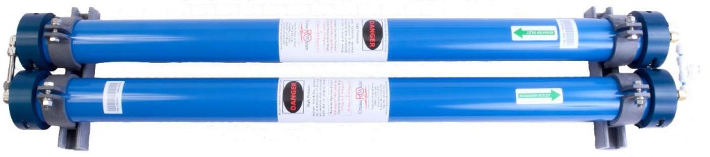
Most watermakers have two large components, and various smaller components, hoses, and tubing. The reverse osmosis (RO) pressure vessels are 44˝ long and about 3˝ in diameter each. The high-pressure pump that forces the water through the RO membranes has a rather large and heavy 1hp electric motor with a high-pressure pump attached to it. It’s about 10˝ in diameter and 18˝ long and weighs about 50 pounds. Both the pressure vessels and the high-pressure pump need homes on our boat.

I usually make cardboard mockups of large things to ensure they will fit in the space intended. I’ve done this with our holding tank and freshwater tank. This gives me the ability to move the mockup around to find the best fit. In my opinion, this is the single most important step to installing anything that has any size to it. So, I bought some 3˝ in diameter mailing tubes and cut them to the exact size of the two pressure vessels. I then mocked up the high-pressure pump with some cardboard to simulate its relative sizes.

Available space

After a bit of trial and error, I was able to find a place under the cabinet behind the port settee where both pressure vessels would fit. Normally the pressure vessels are mounted with hardware that sets the two side-by-side. I didn’t have the room to do this, but I did have the room to mount them individually in that space. This would require separate mounting hardware and an extra hose with different hose fittings to connect the two pressure vessels. I consulted with the manufacturer on this and they said it wouldn’t be a problem.

The only place I found where I could mount the high-pressure pump was under the “L” portion of our port settee. There physically was room, but the hull slopes up in that area, so I needed to build a shelf to sit the high-pressure pump on. After testing these locations with my mockups, I was confident they would fit, so I placed the order for the 30gal/hr watermaker.

Installing the components

The instruction manual that comes with this watermaker is quite complete. It details how the components go together, the flow of both salt and fresh water, and how to wire the two pumps. Exactly how it all fits together is determined by the location of each component from one another and the obstacles the hoses and tubing have to go around or through.

Installation drawing

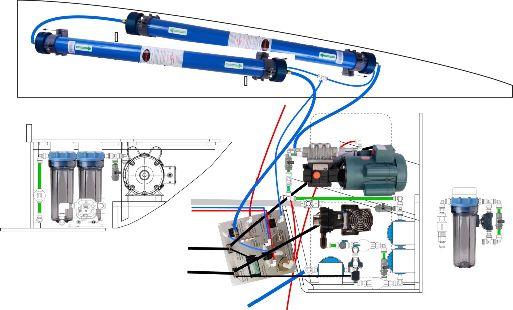
After studying the manual, I used Adobe Illustrator to make a drawing of how the components would be connected within the space I had available for them. I went through several iterations of drawings until I had one that I felt worked best. I now had a drawing that showed every valve, elbow, and length of tubing I needed, and how they would fit together.

The kit came with quite a bit of tubing of several sizes and a bag of fittings. I took inventory of the fittings to see if I had the fittings I needed based on my drawing. I was shy a few, so I found a source online to purchase the extra fittings I needed.

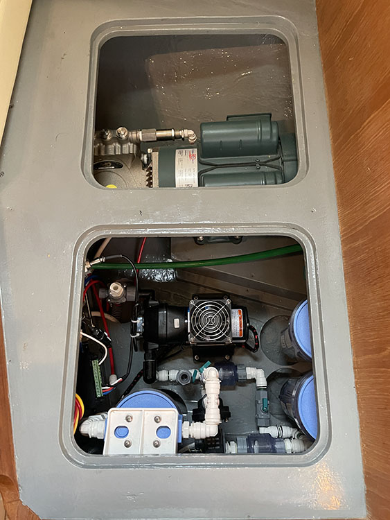
It seemed best to install the two largest components first, the pressure vessels and the high-pressure pump, as these could only be mounted in the spaces I identified for them using the mockups. As they were big and heavy, they were going to take the most time to mount. All the hoses, tubing, filters, and boost pump were small, and I had enough room in the locker to mount them without issue.

New access hatch

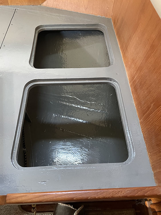
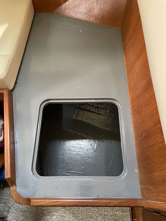
Our boat had one access hatch for the “L” portion of the settee. This didn’t give me enough room to mount the high-pressure pump, so I cut a second hatch over the space where the pump was going. I then built a plywood shelf and epoxied it onto the hull. This took a bit of time, but I felt it was necessary for a proper installation of the heavy high-pressure pump.

Rubber motor mounts

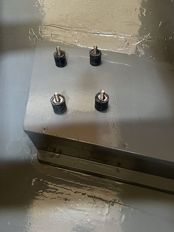
The high-pressure pump motor has a metal base with four bolt holes to attach it to the shelf. It didn’t come with any vibration dampening mounts, so I found some online that would do the job nicely. These mounts would prevent the motor vibration from transferring to the hull, hopefully keeping the noise from the motor down a bit. Before I mounted the motor, I connected the wiring and pressure relief valve tubing as they would have been difficult to connect once the motor was in place.

Pressure vessel installation

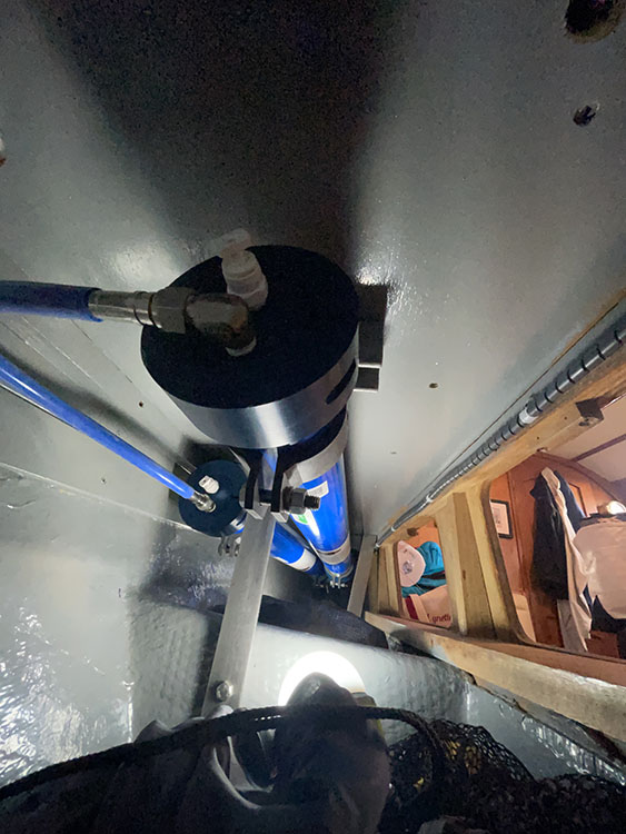
Next, I mounted the pressure vessels under the cabinet. Other than being a tight fit, I was able to get them mounted easily with some help from my wife. I also attached the high-pressure hoses and the freshwater tubing at that time so the pressure vessel portion of the installation would be complete.

The water flow for the watermaker requires two through hull fittings; one for the seawater intake into the watermaker and one for the waste brine to exit. I already had a through hull for the intake, so I only needed to drill a hole above the waterline and mount a small through hull for the waste brine.

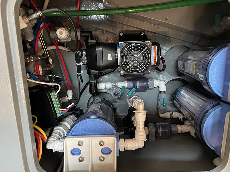
Once the through-hull was mounted, I installed the three filter housings and connected the components with the tubing and fittings as per my drawing and the instruction manual. The locker below the settee didn’t have enough headroom to unscrew the filter housings and remove the filters, so I had to cut holes in the floor below the filter housings to allow the housings to be lowered enough to get the filters in and out. Luckily I had about 4˝ of space between the hull and the floor of the locker. I decided not to mount the boost pump until I had all the tubing installed and the hose from the through hull installed. That way I could place the boost pump exactly where it needed to be to connect to the tubing and hose.

Control Panel

Probably the most difficult task was to snake a ¾˝ hose from the through hull under the galley sink to the locker where the watermaker was being installed. It was about a 15´ run and required drilling some holes in very inaccessible locations to get the hose installed. At the same time, I wire-tied two ¼˝ tubes that supplied fresh water to the water tanks and sample water to one of the sink foot pump faucets for testing. This way, when I installed the ¾˝ hose the two tubes came along for the ride. Once the ¾˝ supply hose was installed I was able to install the boost pump in exactly the correct location to connect to the supply hose.

This watermaker has a very nice control panel with everything needed to run the watermaker. I cut a hole in the side of the settee to mount the control panel. Some of the tubing and hoses had to be attached to the back of the control panel. Once that was done, the liquid side of the watermaker install was finished.

Our watermaker uses both 120vac and 12vdc. I had to add a breaker to each electrical panel and run two sets of wires from the panel to the watermaker control panel. The 120vac is for the high-pressure pump and the 12vdc is for the boost pump. I wired the high-pressure pump into the normal house 120vac panel so I could use the inverter to power the watermaker when the engine was running or hook the Honda generator to the shore power cord to run the watermaker when we weren’t running the engine. That way I had two sources to power the high-pressure pump that were convenient to use.

Commissioning the watermaker

Finished installation, top view
Finished installation, full view

Once the electrical was done it was time to test for leaks and commission the watermaker. We made a short trip out of the marina in Barra de Navidad to be in clear water for the testing. The instruction manual gives great instructions on commissioning the watermaker, so after reading that portion of the manual, I proceeded to test the watermaker. As soon as both pumps had run for a bit and the air was purged from the system, I increased the pressure on the RO membranes. When the RO membranes had about 800psi of saltwater pressure the watermaker was making about 30gal/hr of fresh water. I then checked for leaks all along the plumbing. Luckily there were no leaks.

Watermakers require frequent freshwater flushes of the membranes when not in use to prevent the buildup of bacteria and organisms. I set an event in my Google Calendar to remind me every three days to switch on the freshwater flush for 3-5 minutes. Some watermakers have a feature to do this automatically. Ours had an option we could purchase, but we decided it was simple enough to do it manually. Less to go wrong in my opinion. Yes, I have to remember, but it’s not the end of the world if I forget one time here and there. If we plan to be gone for an extended period, I will just prepare the membranes for extended storage. This is called pickling the watermaker and isn’t too difficult to do.

In summary

Plan, plan, plan, and read the manual. Installing our watermaker wasn’t an overly complicated process. Simple knowledge of plumbing and electricity is necessary, along with the ability to read a manual and follow the instructions. Building both physical mockups and digital ones in Illustrator was important for me, as I like to have a plan I can follow.

We can now make water anytime we want as long as we are in reasonably clean water, which is usually when we are on passage. We’ve filled the two 45gal tanks multiple times now and the water tastes great. We are now finally freshwater-independent!

Repower with a Beta43 engine

When we purchased our 1980 Fast Passage 39, No Regrets, back in 2004 we felt the Perkins 4.108 engine was a good, solid engine with low hours. We had no intention or budget to replace the engine. However, we did a major refit of the boat over the next 15 years, including all new wiring, plumbing, standing rigging, running rigging, sails, dodger, bimini, and electronics. Of course, the refit took longer than we ever anticipated, partly due to available funds and partly due to a lack of available time. Probably the single biggest gain from this refit is that I know everything about all the systems on the boat, so maintaining these systems should be easier to do myself.

With only a few non-critical items still left on our to-do list, we did a shakedown cruise up the coast of Washington in 2018. We noticed that the exhaust had some light gray smoke, which hadn’t been present on previous trips. During this shakedown cruise, we put about 100 hours on the engine and consumed 1.25 gallons of oil. Yes, that’s 1.25 gallons! Luckily, we had that much spare oil on the boat, so we were able to keep the engine running.

We had no idea where the oil was going. If it was being burned, there would have been some reasonably heavy black smoking trailing behind the boat and the transom would have been black with soot. Neither of which had happened. So where was it going?

Old Perkins engine front

I contacted our boatyard and asked them whom they would recommend looking at the engine. I contacted that person and had him come to the boat to check out the engine. He was stymied as it wasn’t clear where the oil was going. The engine sounded strong and started immediately with no issues. We had an oil analysis done, indicating some metal in the oil, but nothing serious. He suggested a compression test and if there was a cylinder with low compress, do a leak-down test on that cylinder to identify where the leak was. So, I purchased a diesel compression tester on eBay and then purchased a leak-down tester online. The compression test indicated I had lower compression on the #1 cylinder, so I performed a leak-down test on that cylinder. The leak-down test showed that the intake valve wasn’t sealing. This prompted a head rebuild, so I took the head off and had it rebuilt.

Old Perkins engine rear

Once I reinstalled the rebuilt head, we took two separate trips around Sauvie Island. On the first trip, we consumed about 1/2 quart of oil in almost 8 hours. The second trip showed we hadn’t consumed any more oil. Success? I wasn’t convinced we wouldn’t have more issues down the road and had lost my confidence in the engine. The Perkins was built in 1979 and we were planning an extended voyage outside the USA. It was time for some serious discussion and thought.

I did some research to get an idea of the cost of new vs. rebuilding the Perkins. My wife, Lynette, and I discussed options and costs. We both agreed that a repower was in our immediate future, as it was the only way we would regain confidence in an engine. Yes, we could have rebuilt the Perkins, and there’s plenty of information online stating that the Perkins 4.108 is an excellent, well-built engine that still has parts available. But we would have a rebuilt 1979 engine that could cost 1/2 to 2/3 the price of a new engine.

I had already done a significant amount of research online reading about all the different options for a new smaller marine diesel engine. I wanted a low rpm engine (under 3,000rpm) that didn’t have all the electronic controls the newer common rail engines have. I wanted an engine I could repair that didn’t rely on electronics to run. Plus, I wanted parts to be readily available worldwide. These needs lead us to Beta Marine from the UK. They marinize Kubota tractor engines and have been doing so since 1987. Beta Marine engines met all my criteria stated above. We now had our engine manufacturer, but what size?

I had read that many sailboats have engines that are too large for the boat and therefore are not put under optimum load. Diesel engines like to be run with a good load, and an engine that is too big for the boat can be run without enough load to keep them in an optimum heat range. More load on an engine means the engine will run at a higher temperature, which is better for the engine than being run with too little load, causing the engine to run at a cooler temperature.

With this research, we opted to replace the 50hp Perkins with a 43hp Beta. This saved us several thousand dollars over a 50hp Beta and roughly 150 pounds over the existing Perkins. Beta makes a conversion kit that would allow us to use our existing Velvet Drive transmission. Unfortunately, that combination was too long to fit in our engine compartment, so we opted to go with one of Beta’s standard transmissions, the Technodrive TMC60A, which has a 7º down angle for the driveshaft. The 7º down angle allows the engine to be installed quite low in the engine compartment keeping the weight low and giving us some much-needed space above the engine.

Since I had done most of the refit myself, I also wanted to do most of the repower myself. Hopefully, this would save some money and allow me to know as much as possible about the engine installation so I could perform most repairs myself.

The boatyard told me that outside the cost of the engine a significant cost of a repower was in rebuilding the engine mount rails to fit the new engine. Based on this, I wanted to use the same engine mount rails that the Perkins sat on with no modification. This would require less customizing of the engine compartment and hopefully save us money. Since the Beta 43’s motor mounts are in different locations than the Perkins motor mounts it would require customizing the engine mounting feet. Beta offers this service and has several customization forms to provide the measurements needed to fabricate custom feet.

I have some skills in using Adobe Illustrator, so I used that program to draw the engine compartment to scale. Beta has CAD drawings of their engines with different transmissions that I was able to import into Illustrator. I played with several transmissions attached to the engine to see which one would fit in the engine compartment best. This is how I chose the TMC60A as the transmission. It fit the best and didn’t add additional cost to the engine, as it was one of the standard transmission options.

Engine drawing in Illustrator

From there I played with different positions for the engine and transmission that would require the least amount of customizing of the engine compartment. Once I arrived at the best fit, I filled out the customization forms and sent the forms and my plans to Beta. They entered the measurements in their CAD program and sent me back the resulting CAD drawings. I placed those drawings into Illustrator to see how the motor mounts would fit. It took about 4-5 tweaks back and forth before we had the final solution.

The fit of the engine was going to be quite tight in the engine compartment, so I had Beta configure the engine with the oil filter in the rear above the transmission, which made it much easier to change the filter. Normally it’s down low and on the forward starboard side of the engine. Beta makes a remote oil filter kit, so I had them make a mounting bracket to hold the filter above the transmission. That was a very good decision as now the filter is easily accessible and mounted vertically instead of horizontally (no oil running all over the place when changing the filter).

Old Perkins engine, ready for removal

With the planning and configuration behind us, Beta started the build process on our engine. It took about a month to receive the engine. Before the engine arrived, we hauled the boat, and I began dismantling the Perkins for removal. I wanted to make it as easy as possible to remove the old engine and protect the woodwork from damage, so I padded everything that could get damaged with 1/2˝ thick honeycomb cardboard and pipe insulation to cover corners. I took everything that was attached to the engine, including the head, off the engine. I didn’t remove the transmission until we had the crane over the boat and the cable wrapped around the transmission to haul it out. From start to finish once the crane was over the boat, it took about 1.5 hours to get the old engine and transmission out of the boat and onto a pallet that I built for the engine.

Engine bed, ready for new engine

With the engine out of the boat and while waiting for the Beta to arrive, I cleaned and repainted the engine compartment. I filled the old mounting holes as the new feet didn’t fit those holes. I also remeasured the entire engine compartment to make sure my measurements were correct, as it was difficult to take accurate measurements with the engine in place. I’m glad I did as the measurements had been slightly off.

When the engine arrived, I unboxed it and prepped it to lift into the boat. This meant taking some things off like the alternator and a few other items that stuck out. I didn’t want to completely dismantle the engine as I had done with the Perkins as it was a new engine ready to run. I didn’t even want to remove the transmission if at all possible. We swung the engine into place over the companionway and lowered it into the boat. We needed to turn the engine 90º to move it into the aft berth and then another 90º to position it for insertion into the engine compartment.

New engine, on its way to the boat

I must say, getting the new engine into the boat was a major task. It’s a tight fit with very little room to move the engine. The engine compartment is situated between the aft berth and the galley. It occupies space under a bureau in the aft berth and one of the counters in the galley.

So here we were with a 500-pound engine hanging off a cable in the middle of the companionway with no room to turn the engine 90º. I grabbed some wrenches and started removing other parts that were still attached to the engine. Finally, I had enough off the engine that we could turn it 90º and get it into the aft berth. We put some boards down to slide the engine into place, and I attached a come-along between the front of the engine and the mast and ratcheted the engine into position. Whew! The engine was finally in position. All this took about 2.5 hours.

New engine hanging in aft berth

Because it was costing us money to be in the boatyard, we decided that I wouldn’t finish the install at the yard, but rather tow the boat back to my slip to finish the install at my leisure. Since the engine and transmission were shorter than the old engine, we had to purchase a longer propeller shaft, which couldn’t be fabricated until the engine was in position, as it was necessary to have a very accurate measurement for the shaft length. This meant I had to position the engine in its final position and bolt it down. To do this I purchased a shotgun sighting laser and installed it in an aluminum tube that fit tightly inside the shaft log. I then shot the laser at the coupling on the transmission and moved the engine and transmission up, down, left, and right so the laser dot was positioned in the middle of the shaft coupling. We then drilled holes and bolted the engine in place. I then measured the length for the shaft and had it fabricated. Once the shaft arrived, we installed it and splashed the boat.

Since I had unlimited towing with BoatUS I asked TowBoat if they would tow my boat back to my slip. Since I hadn’t used the towing service, they said they would do it for free, so off we went to our slip with the TowBoat side-tied to our boat. All this went without a hitch.

Exhaust elbow fitting

Over the next couple of months, I finished installing all the electrical, plumbing, exhaust, and fuel systems. The exhaust elbow needed to be customized, so I used some 2˝ PVC pipe and elbows to construct a model for the fabricator. He used the original exhaust elbow cutting off some elbows and tack welding them back on for a dry fit. The elbow didn’t quite fit right, so I took pictures and showed the fabricator what needed to change for a perfect fit. He made the modifications and finalized the welds. The customized exhaust elbow fit perfectly.

Once all the systems were connected to the engine it was time to start the engine for the first time. A quick push on the starter button and the engine started immediately. I found two leaks, so stopped the engine and spent some time trying to fix a leak around a hose going to the heat exchanger and a leak around the coolant filler cap.

After several email conversations with Beta, we identified the issues. I found that the radiator cap leak was caused by a bent coolant cap filler neck (where the cap is attached to the engine). The leak at the heat exchanger was due to a poorly made bronze casting that had a hole in it. A quick email to Beta Marine and we had replacement parts on their way. Once I installed the parts, we had no more leaks!

New engine, almost finished

Success! We now have a new engine that is way better than the Perkins and more importantly, we have an engine we have confidence in. Total cost is a bit difficult to establish, as we always wind up doing multiple projects while on the hard. We replaced the rudder, changed the 3-blade MaxProp to a 4-blade MaxProp, and realigned the propeller shaft strut as it wasn’t quite in alignment, causing some wear on the strut cutlass bearing. Plus, we had the ablative bottom paint sanded off and two coats of hard bottom paint put on. So, after all this, my best guesstimate is somewhere slightly less than $20,000. The engine with customization and shipping was about $16,500. This included a 220 Amp Balmar alternator, MC614 regulator, and a coolant expansion tank as our water heater is above the engine, requiring a coolant expansion tank to be installed above the water heater to prevent air pockets in the coolant lines. We now have about 120 hours on the new engine traveling down the coast to San Diego with no issues at all. The engine ran at about 170º F, consumed no oil, and had enough power to motor between 5.5 and 6.5 knots (depending on conditions) at about 2000rpm using between 0.6 and 0.8 gallons per hour. Wide open throttle pushes the boat at about 7 knots using about 1.3 gallons per hour. We’re very happy with the Beta engine and the refit.